FIG PUBLICATION NO. 56
Guidelines for the
Planning, Execution and Management of
Hydrographic Surveys in Ports and Harbours
FIG Commission 4
Working Group Hydrographic Surveying in Practice

Contents
Foreword
Acknowledgements
1. Introduction
2. Scope
3. Reference to Other Hydrographic
Standards and Guidelines
3.1 Overarching International Standards
3.2 National Hydrographic Standards
3.3 Guidelines & Standards of Good Practice for Hydrographic
Surveys
4. The Port Environment
5. Risk Assessment
6. Survey Equipment
6.1 Depth Measurement Equipment
6.2 Positioning System Equipment
6.3 Motion Sensor Equipment
6.4 Tide Gauge Equipment
6.5 Survey Vessel Equipment Offsets
7. Equipment Calibrations
7.1 SBES Calibration
7.2 MBES Calibrations
7.3 Tide Gauge Calibrations
7.4 Miscellaneous Checks & Calibrations
8. Data Collection
9. Data Processing
10. Data Analysis
10.1 Accuracy of Soundings
11. Data Presentation
12. Datums
12.1 Horizontal Datums
12.2 Vertical Datums
13. Digital Data
14. Hydrographic Surveyor
Competencies
14.1 Hydrographic Survey Qualifications
14.2 Hydrographic Survey Certification
14.3 Demonstrable Experience
Orders for printed copies
Since 1994, when FIG Publication No. 8, a report entitled Hydrography,
Ports and Harbours, was first published, the widespread adoption of the
Global Navigation Satellite System (GNSS) and Electronic Nautical Charts
(ENC) have brought on notable changes to hydrographic survey technology and
how nautical data is published. The thought of publishing a set of good
practice guidelines on port hydrography came to mind with awareness that in
some jurisdictions the responsibility for port surveys was being divested
from the national hydrographic offices to individual port corporations. In
this case, some ports took up the challenge, made the investment and built
their capacity to survey while others found themselves with neither the
know-how nor technology or experience to conduct their own surveys and to
furthermore transform their data into chart products (electronic or
otherwise).
Since FIG Publication No. 8, GNSS has become the premier tool for navigation
and precise positioning. Terminology such as minimum under keel clearance has
taken on new meaning considering the lower risks associated with navigating on
electronic chart products built from high-resolution bathymetric data, corrected
with real-time water level information. Tonnage is money, and increasing port
capacity for increased vessel tonnage requires up-to-date and accurate
hydrographic information. The intent of this new publication is not to bury the
reader with excessive detail, but to provide an overview of current hydrographic
survey technology and techniques and to point out authoritative sources for
information relevant to the execution and management of hydrographic surveys in
ports and harbours.
For this I would like to thank the members of Commission 4 Working Group 4.1,
members of the Hydrography Commission of the Surveying and Spatial Sciences
Institute (SSSI), the Australasian Hydrographic Society and the New Zealand
Institute of Surveyors, for their efforts in compiling this new publication.
Andrew Leyzack, C.L.S.
Chair FIG Commission 4, 2007–2010
The following organizations, publications and individuals assisted in
compiling this document and their help is gratefully acknowledged:
- Maritime New Zealand – Final Guidelines of Good Practice for
Hydrographic surveys in New Zealand Ports and Harbours (2004)
- Ports Australia – Principles for Gathering and Processing Hydrographic
Information in Australian Ports (V1.4 November 2008)
- Maritime Safety Queensland – Standards for Hydrographic Surveys within
Queensland Waters (May 2007)
- International Hydrographic Organization – IHO Standards for Hydrographic
Surveys, Special Publication No 44 (5th Edition February 2008)
- Maritime and Port Authority of Singapore – General Specifications for
the Conduct of Hydrographic Surveys (May 2002)
- Mr David Mundy – iXSurvey Australia Pty Ltd, Brisbane, Queensland,
Australia
- Mr Simon Ironside – Eliot Sinclair & Partners Ltd, Christchurch, New
Zealand
- Mrs Venessa O’Connell – Sydney Ports Corporation, Sydney, New South
Wales, Australia
- Mr Robert Slater, Mr Giles Stimson & Mrs Elizabeth Tutty – Port of
Brisbane Pty Ltd, Brisbane, Queensland, Australia
- Mr Barry Smith – Geocomp Systems Pty Ltd, Townsville, Queensland,
Australia
- Mr Michael Christensen & Mr Shaun Shahrestani – The Port of Los Angeles,
San Pedro, California, USA
- Commodore Rod Nairn RAN – Australian Hydrographic Service, Wollongong
New South Wales, Australia
- The Surveying and Spatial Sciences Institute, Canberra, ACT, Australia
- The New Zealand Institute of Surveyors, Wellington New Zealand.
Hydrographic surveys of ports and harbours are undertaken primarily to
support the safe navigation of vessels. Port authorities are charged with
maintaining and developing their harbours with regard to harbour use, and the
size of vessels the harbours accommodate. This duty of maintenance covers
several specific requirements, including the execution of hydrographic surveys.
To meet increasing demands for volume and efficiency, ships are becoming
larger and, with maximum loading, under keel clearances are diminishing.
Consequently, there is an increased burden of responsibility on port
administrators and surveyors to ensure that hydrographic surveys are undertaken
to appropriate standards by appropriately qualified personnel.
Accordingly, these guidelines have been prepared to provide an overview of
good practice for port administrators and surveyors striving to develop the
capacity to either conduct their own hydrographic surveys, or to contract this
work to a third party.
The guidelines are intended for use in ports and harbours where hydrographic
surveys are carried out to support safe navigation of vessels. They are based on
widely accepted good practice for the planning, execution and management of
hydrographic surveys. The guidelines should be used by those responsible for the
provision of hydrographic information when determining the hydrographic aspects
of risk relevant to the safe navigation of vessels within their jurisdiction.
3. Reference to Other Hydrographic
Standards and Guidelines
Standards and guidelines for hydrographic surveys relating to safe navigation
generally fall into one of three levels, each with differing content and
application.
3.1 Overarching International Standards
The overarching standards, the highest level for hydrographic surveys, are
those adopted by the International Hydrographic Organization (IHO). They form
the basis from which IHO member states can produce their own national standards,
and are intended to ensure a consistent quality of hydrographic information
contained on internationally recognised nautical charts.
The set of minimum criteria that must be met to achieve a recognised level of
accuracy, or ’Order’ of survey, is set out in Special Publication No. 44
Standards for Hydrographic Surveys (S-44), produced by the IHO, and now in its
fifth edition. Typically, Special Order, or Order 1, applies to surveys of ports
and harbours. Order 1 does not provide detailed survey methodology, but it does
include broad guidance on key areas. The IHO Manual of Hydrography (M-13)
provides more specific details of the application of surveying methodology.
Reference should be made to S-44 for standards relating to the broader
science of hydrography, and particularly for authoritative definitions of common
hydrographic terms. S-44, and the Manual of Hydrography, can be downloaded from
the IHO website at http://www.iho.ohi.net/.
3.2 National Hydrographic Standards
Second level or National standards are produced by IHO member states. They
are predominantly based on S-44, and modified to suit each country’s unique
requirements. These standards are usually quite detailed and contain
considerable prescriptive processes. Similar to S-44, their purpose is to
provide minimum standards for the capture of hydrographic survey data to support
the production of official nautical charts.
3.3 Guidelines & Standards of Good Practice for
Hydrographic Surveys
Third level guidelines and standards are often produced by agencies and
organizations to describe good practice and procedures for specific hydrographic
surveys. The scope of such guidelines is often narrower than national standards,
and focuses on key areas of hydrographic surveying that support a particular
type of operation, e.g. hydrographic surveys in support of port operations. The
United States Army Corp of Engineers, for example, publishes a document
pertaining to pre and post dredging surveys.
Most ports and harbours have dredged channels, berths and anchorages, which
suffer from siltation, thereby reducing the depth of water available to
shipping. Ports operate with a minimum under keel clearance that must be
maintained by a ship transiting a port. Regular surveys are required to monitor
the published depth, as charted depth accuracy is a significant component of the
calculation of a port’s under keel clearance. Minimum under keel clearance can
be determined by anticipating the following contributing factors:
- vessel squat and settlement (related to speed)
- vessel manoeuvring characteristics
- vessel draught as affected by roll, pitch & heave movement
- accuracy of the predicted or measured tide
- accuracy of published depth
- rate of siltation since last survey
- sea state (wave height), direction & tidal stream.
The hydrographic surveyor contributes to the measurement of factors such as
tidal height, accuracy of declared depth, and the required frequency of
hydrographic surveys. The surveyor may also contribute expertise necessary for
the measurement of a vessel’s squat and roll, pitch and heave movement.
Various methodologies exist for the collection, processing and presentation
of hydrographic survey information. Whilst the presentation of such information
is largely determined by the needs of the end user, the fundamentals of
hydrographic data collection remain the same, i.e. the accurate measurement of
water depth (Z) below a stated datum, and the position of this measured depth
(X,Y). Additionally the hydrographic surveyor would be concerned with
determining bottom type and as well the positioning of “intertidal” and
shoreline features above a stated datum.
The widely accepted method for obtaining depth data has been with a
single-beam echo sounder (SBES), with position provided by electronic ranging
equipment. Positioning has been made easier with the advent of the Global
Positioning System (GPS), particularly in differential (DGPS) and real time
kinematic (RTK) modes. The introduction of the multi-beam echo sounder (MBES)
has provided the ability to ensonify and measure much greater areas of sea floor
to a higher level of detail, but it also requires greater knowledge to use this
technology effectively.
As all hydrographic survey data has some degree of uncertainty, it is
important to ensure that charted depths are accurate, and that the charted depth
tolerance is commensurate with the allowance made for under keel clearance at
the port.
S-44 requires that hydrographic surveyors include with their survey data, a
statistical estimate of the probable error. It is important that the estimate of
the depth error is based on the survey methodology adopted; the equipment used
to perform the survey, and is unambiguously reported for each survey undertaken.
Furthermore IHO S-57, the current standard for electronic nautical chart (ENC)
data exchange prescribes standards for encoding metadata to identify areas based
on specific depth and positional uncertainties called Zones of Confidence or
ZOC.
The varied and dynamic nature of ports and harbours dictates that the
frequency and methodology for hydrographic survey operations should be
determined primarily by a risk assessment, rather than by the blanket adoption
of a set of rigid criteria. The usefulness and credibility of associated risk
assessments largely depend upon the quality of the balanced and quantifiable
information on which they are based. Hydrographic factors for consideration in
risk assessments should take account of the stability of the seabed and depth of
available water in relation to vessel draught, as well as intended development
that will affect the navigable depth in a given area.
Assessments should be undertaken in a rigorous manner. An important product
of the risk assessment is a plan that sets out the requirements for surveys,
including the type, extent and frequency. Other considerations include (but are
not limited to):
- vessel type and operations (i.e. high speed, restricted in ability to
manoeuvre etc)
- potential environmental impact of a hydrographic-related event
- quality/reliability and/or uncertainty of existing hydrographic
information
- complexity of the area to be surveyed
- stability of seabed
- depth and width of navigable water in relation to vessel draught
- regional development
- fairway design
- reports arising from vessel groundings or reported depth discrepancy
- competency of persons responsible for the surveys.
Equipment to be used during hydrographic survey operations falls within the
broad groupings of equipment to measure depth, to establish position, and to
measure water level (e.g. automatic tide gauges). Generic considerations for the
use of such equipment are covered in this section.
Advances in survey equipment technology have enabled some processes to be
automated, thus significantly reducing the level of user input in normal modes
of operation. It is vital, however, that users possess a reasonable
understanding of the capabilities and limitations of the equipment used. In
particular, it should be understood that manufacturer’s specifications rarely
guarantee equipment performance, unless the equipment is operated in accordance
with strict parameters and under optimum environmental conditions.
Regardless of the manufacturer’s stated specifications, in accordance with
principles of good practice, the surveyor is still required to identify,
eliminate or reduce, and quantify remaining sources of error in an appropriate
error budget.
As Total Propagated Uncertainty (TPU) values are often estimates based on the
claims of manufacturers, these can be difficult to formulate correctly for a
dynamic vessel. It is therefore suggested that a priori TPU is used to determine
whether the proposed system-package is capable of meeting the required
specifications. A more quantifiable measure, however, should be used to derive
the post priori precision (e.g. from comparison of the results of tie
line/interline and previous data).
6.1 Depth Measurement Equipment
Depths are normally measured using either single-beam (SBES) or multi-beam
(MBES) echo sounders. Complete seabed ensonification for the purpose of small
target detection can be achieved when these systems are used in conjunction with
a towed or fixed side scan sonar system.
It should be noted that SBES is still the most common tool used in port and
harbour surveys and will continue to give valid results when used correctly in a
well planned and executed survey. Multi-transducer, single beam (Sweep) systems
are becoming less popular in favour of shallow water, wide swathe or dual head
multi-beam sonar systems. However, until capital and operating costs reduce
significantly, it is unlikely that, in the short term, MBES will replace SBES
for routine surveys in the average port or harbour.
6.1.1 Single-Beam Echo Sounder
SBES must be calibrated by a bar check to correct for errors in the speed of
sound in the water column, and to set the correct transducer draught. The latter
is to ensure that the instrument records the depth below the sea surface and not
below the transducer. Where no sound velocity profile data is available, a bar
check should be conducted at least daily, and on any change of survey area
during the day, to ensure consistent data quality. Likewise a bar check must be
conducted when any SBES components are modified or replaced on the vessel.
6.1.2 Multi-Beam Echo Sounder
MBES as a hydrographic survey tool has significant advantages over SBES in
its ability to detect small objects and achieve full bottom coverage. It
requires key ancillary equipment such as an appropriate motion and heading
sensor, which must be properly integrated for correct operation. The ability to
measure sound velocity (SV) profiles through the water column (in some cases
continuously) is required to correct for the refraction of beams, particularly
where shallow water systems employ wide swathe widths. MBES with flat transducer
arrays also require an accurate instantaneous measurement of the sound velocity
at the transducer face to enable correct beam steering to occur.
Users should be aware of the expected performance of the system and employ
robust methodology to prove this before accepting the system as operational.
Careful calibration of MBES is required at regular intervals thereafter. Good
practice calls for the use of a reference surface, an area of seafloor where
repeatable measurements can be compared. Inherent with the increased detail and
coverage achieved with MBES is the ability to clearly see errors associated with
incorrect lever arm and sensor offsets, time delays, sound velocity and
excessive vessel motion. The ability to ‘average’ or ‘smooth’ out such errors in
subsequent processing is potentially misleading and should be avoided unless the
magnitude of the change from the raw to the smoothed record is clearly stated.
Such errors should be included in the calculation of the overall accuracy value
accompanying the data.
6.2 Positioning System Equipment
Differential GPS is widely used to fix vessel position during hydrographic
surveys. The source of the differential corrections should be proven by
comparison with a known survey control point, particularly if a local base
station is established. GPS receivers should be configured to output positions
in the desired datum (normally WGS84) with associated quality tags. The quality
of the position fixes should be monitored during sounding operations through
examination of the GPS parameters in use (number of tracked satellites, dilution
of precision (HDOP and PDOP), etc), and real-time comparison with a second
positioning system is recommended. Post-processed differential is an alternative
to RTK in instances where a high accuracy positioning solution is required.
Users can navigate with a Satellite Based Augmentation Service (SBAS) such as
WAAS while logging raw GPS aboard, and simultaneously at a reference (control)
station ashore.
Real time kinematic GPS offers increased precision of the horizontal
position, provided that the footprint of the echo sounder in use is of a
comparable dimension. Users of the sounding data need to be aware that the
horizontal accuracy quoted for an RTK GPS survey (or any other positioning
system) may be affected by the beam width of the echo sounder. If the beam width
is large, an increase in depth will increase the footprint on the seabed and
degrade the actual positioning of the soundings. This is, potentially, more of a
problem with SBES as MBES beam width is usually much smaller. Additionally the
accuracy of position of the soundings will be improved with the use of motion
sensor equipment.
6.3 Motion Sensor Equipment
The demand for greater transparency in the derived accuracy of soundings
taken in swell conditions has seen the use of motion sensor equipment become
standard in an increasing number of port and harbour surveys.
The accelerometer is the standard type of motion sensor equipment, and
different units range in their complexity, and in the precision they are capable
of achieving. The correct installation and definition within the vessel
reference frame is vital, and consideration should be given to obtaining
assistance from the manufacturer if the user is unfamiliar with the equipment.
Kinematic GPS is becoming increasingly popular as an alternative method of
correcting vessel motion, either in conjunction with, or in lieu of,
accelerometer-based motion sensors. While providing a low cost alternative for
measuring roll, pitch and heading, the update rate of the GPS (typically 10Hz)
limits its ability to serve as an accurate heave measurement sensor. Thus, users
of both types of motion sensors should take all practical steps to check their
correct operation, preferably by some means of ground-truthing (e.g. quantifying
the motion error residual in data collected over a known flat seabed).
6.4 Tide Gauge Equipment
Sea level (tide) measurements of height and time are required to reduce
collected soundings to Chart Datum, and they are subsequently used (as a
continuous record over long periods) to define tidal reference levels (e.g.
MHWS). Tidal observations are normally obtained via automatic recording gauges,
which are permanently installed in many ports.
Other methods used to obtain tidal information include: manual tide pole (or
staff) readings, referenced to a recognised datum (normally Chart Datum); and
RTK GPS with centimetric precision in the vertical (Z) dimension. This latter
method provides a total height measurement, including tide height, but the
geoidal separation must be accurately known, and the base station-rover range
limitations clearly understood.
If Kinematic GPS is used in this manner, it is considered good practice to
regularly correlate the results against tidal observations obtained by
traditional (e.g. tide gauge) methods. Regardless of the type and method used,
the equipment must be capable of measuring the tide to the required accuracy. If
the method of tidal reduction requires interpolation between individual
observations, the interval between observations must be such as to provide an
adequate representation of the tide curve.
If automatic tide gauges are used, these must be regularly calibrated against
a staff gauge to ensure their accuracy. The accuracy of the tide readings used
to reduce soundings impacts directly on the overall accuracy of the survey.
6.4.1 Tidal Records
In addition to the use of tide readings to reduce sounding data, a continuous
record of tidal data (at least one lunar cycle of measurement) is important for
the maintenance of accurate predictions for the port. It is recommended that an
unbroken record of tidal readings is maintained and archived (accompanied by
relevant calibration records) for this purpose.
6.5 Survey Vessel Equipment Offsets
The position of the various sensors on the survey vessel should be carefully
measured in relation to a common reference point, and correctly applied within
the survey acquisition or post processing software. This information must be
included in the survey documentation. Furthermore, it should be noted that not
all equipment and software engineers adhere to the same conventions when
applying the axes and arithmetic signs used to describe a vessel’s [Cartesian]
reference coordinate system.
Preparation for the survey involves the planning of hydrographic observations
and ancillary activity necessary to support the collection of data, the most
important of which is calibration of the surveying equipment. Equipment
calibrations need to be conducted at regular intervals and documented in order
to support the quality estimate given to the final survey dataset. Maintaining a
data-pack for key equipment, and/or including the relevant information in a
final report accompanying each survey, is recommended.
7.1 SBES Calibration
Calibration of SBES is normally achieved by the bar check method whereby a
bar is set horizontally beneath the transducer on marked lines at pre-determined
depths, and the echo sounder recorder is adjusted so that the echo trace from
the bar appears at the correct depth as determined from the lowering line marks.
Details of this method can be found from references such as the Admiralty Manual
of Hydrographic Surveying, Hydrographic Department, (UK) Ministry of Defence,
1965, or Ingham, A.E., Hydrography for the Surveyor and Engineer, 2nd Edition,
Crosby Lockwood Staples, London, 1987.
7.2 MBES Calibrations
Initial calibration of MBES equipment is a complex task. It is strongly
advised that assistance is sought from the manufacturer, and, if necessary, a
hydrographic surveyor with MBES experience.
Individual MBES error tolerances are much smaller than for SBES. The results
will only be as good as the accuracy of the sensors installed in the system, and
the quality of each sensor with respect to the manufacturer’s quoted accuracy.
Check calibrations or rigorous confidence checks are required at regular
intervals, starting at daily intervals for newly installed systems, and after
significant component upgrade/change to key sensors. Once repetitive results for
calibration values are obtained, checks should be carried out weekly and
monthly. It is recommended that each organization performing surveys with MBES
set up their own regular calibration and inspection/maintenance regime, and
employ a reference surface for ongoing system calibrations. The surveyor needs
to become intimately familiar with all the aspects of the system to be able to
locate and understand small variations in data quality. As a minimum, full
calibrations should quantify the system error sources.
7.3 Tide Gauge Calibrations
It is good practice to confirm automatic gauge readings with the level of the
tide observed on a co-located tide pole or tape, referenced to Chart Datum, at
least weekly, if not daily, during survey operations.
These comparisons provide a valuable record of the gauge performance and
should be retained (e.g. in the equipment data-pack). Where a permanently
recording automatic tide gauge is installed, a full calibration of this system
should be conducted at least annually, or when necessary after maintenance etc.
This procedure involves manual observation of the pole readings over a full
tidal cycle (preferably 25 hours although 12.5 hours may be sufficient) in order
to correlate gauge readings with the theoretically ‘correct’ pole readings.
Further information can be obtained from standard references such as the
Admiralty Manual, or Ingham, A.E. referred to in section 7.1 above.
Regardless of the type of automatic gauge equipment being used to observe
tidal data, confirmation of the tide pole zero against the Standard Port
Reference Benchmark should be carried out by levelling at least annually, or
whenever the pole is moved. Results should be fully documented, and retained
with the tidal archive and/or equipment data-pack. Likewise, the benchmarks that
reference the vertical datum should be checked regularly for movement by a
closed levelling loop.
7.4 Miscellaneous Checks & Calibrations
Regular confidence checks of the vessel positioning system should be
conducted atleast weekly, preferably daily, during the course of a survey. A
static check of the vessel’s derived position against a mark ashore (e.g. a pin
on a wharf ) established to a higher order of accuracy than that required for
the vessel is recommended.
In both SBES and MBES systems, position system latency (time delays) should
also be determined and applied in the survey acquisition or post processing
software. Guidance on determining the latency correction can be obtained from
the equipment manufacturer. Most modern MBES systems use PPS (Pulse Per Second)
timing from a GNSS system to reduce latency down to the millisecond level.
If possible, a dynamic check against a distinctive bottom target for which a
known position has been derived, should be undertaken, as this serves to reveal
any latency or vessel layback errors not otherwise detectable with a static
check. Bottom targets should be located in shallow (i.e. less than 10 m) water
to ensure the echo sounder footprint and subsequent resolution of the target is
comparable with the positioning system in use.
Calibration of ancillary equipment, such as SV probes, should be carried out
by the equipment manufacturer or agent in accordance with the manufacturer’s
guidelines and copies of subsequent certificates should be retained in the
equipment data-pack.
Hydrographic surveys within a port are undertaken for a variety of purposes,
so in the initial planning stage, it is important to establish who will be the
end user of the data.
For example, will the data be used for discovery, charting, safety of
shipping, clearance, under keel clearance, dynamic under keel clearance, volumes
etc? Each end use will have different requirements for the equipment used,
accuracy and precision, and processing and presentation.
Some hydrographic standards prescribe rigid procedures and criteria, but
these may not be appropriate in the port and harbour environment where repeat
surveys are regularly undertaken, and such rigid requirements can be
considerably relaxed. For example, survey line spacing may be increased when
conducting repeat SBES surveys where the likelihood of undetected shoals is
minimal.
Different methods for sounding are required when using either SBES or MBES.
In general, the traditional methods, which involve soundings taken along
parallel lines, at set distances apart according to the desired scale of the
final survey chart, apply to SBES, but are not necessarily appropriate for MBES
operations. Significant differences of methodology for MBES operations include
the orientation of the survey lines in relation to depth contours, and the
varying of line spacing dependent on the least depth of water, which determines
the effective swathe width.
Regardless of the type of equipment used, the running of additional lines
(check or cross-lines) for the sole purpose of validating water level or tidal
reductions is considered essential.
It is important that the limitations of the survey equipment used are fully
considered during sounding operations. In particular, the performance of motion
sensor equipment should be carefully monitored, and survey operations suspended
when it is apparent that the equipment is not coping with existing sea
conditions. This is particularly important in MBES operations where error
tolerances are much smaller.
The tidal regime varies greatly from port to port, and will often require
different survey methodologies to enable appropriate tidal reductions to
sounding data. The ‘hydraulic gradient’ across a survey area can be
considerable, particularly in estuarine-dominated harbours. The use of multiple
gauges to quantify and, if necessary, correct for such an error source, should
be considered. Many hydrographic survey-processing packages have co-tidal
functionality that can be used to correct for this effect.
An imprecise value for the velocity of sound in water during sounding
operations is a potential source of significant error, particularly with MBES
applications, and this should be quantified and, if necessary, an allowance made
for the error.
The effects of squat and settlement on the small vessels typically used for
sounding operations in ports and harbours are likely to be significant,
particularly where the vessel survey speed is above 5 knots in shallow water.
The various techniques used to determine the magnitude of this error normally
involve accurate measurement of the apparent change in vessel draught at various
vessel speeds. It is recommended that trials are conducted to quantify squat and
settlement, and corrections applied if appropriate.
Provided an accurate geoidal separation model can be computed for a given
area, the use of GPS, either real-time or post processed kinematic for precise
vertical measurement, provides an effective means of measuring and applying the
sum of tide, squat, vessel draft and local anomalies.
The processing of hydrographic survey data involves the removal of erroneous
data, and through the selection of valid data, the preparation of a ‘cleaned’
data set for further processing, or for the generation of required products
(e.g. sounding sheets) for subsequent analysis. It is also the stage where tidal
data is normally applied, or where water level data collected and applied in
real-time data acquisition (e.g. from RTK GPS) is validated. Typically, the
practice of running survey check lines will serve to provide a comparison data
set to validate the applied tide reductions, and as well, detect any changes in
vessel draft or squat.
It is recommended that data is processed using a dedicated hydrographic
processing package that preserves data integrity through audit functions, and is
capable of shoal bias thinning. Modern packages offer almost complete
flexibility and the potential to ‘manipulate’ or overly ‘smooth’ data – this
practice is potentially misleading and should be avoided unless the magnitude of
the change in the raw to the smoothed record is clearly stated.
In general, data should be BINed (clashed) rather than gridded, so that
observed depth XYZ’s are preserved. Some software is able to preserve shoal
depths during the smoothing process; however, for charting the CUBE (Combined
Uncertainty and Bathymetric Estimator) surface may be acceptable, while for
volumes, a grid of average depths is generally required.
Where sounding (i.e. field) sheets are produced from gridded data, the
surveyor should refer to the manufacturer’s instructions accompanying survey
processing packages and develop a series of standard operating procedures for
the processing of data, mindful of the above considerations. Where possible,
standard nautical hydrographic symbology should be used on survey sheets; in
particular, the standard convention of displaying depths as metres and
decimetres where the decimetre is shown in subscript form should be followed
(e.g. 56 instead of 5.6).
Data collected during survey operations should be monitored closely to ensure
that the required standard, and the desired extent of coverage, is being met;
however, it is not possible to fully assess the overall quality of work until
all data can be viewed together or in suitably sized blocks. Cross-line or
check-line comparisons and various other consistency checks are undertaken at
this time. Areas requiring re-running, either because of gaps in coverage or due
to suspect data, is identified at this stage.
10.1 Accuracy of Soundings
Perhaps the most crucial aspect of data analysis is the assessment of the
accuracy achieved. Soundings on a chart, sounding sheet, or other plots used as
decision aids in navigation (including post dredge surveys), are meaningless
without associated information on their quality.
The accuracy of soundings cannot simply be estimated without proper
justification. In determining depth accuracy, all sources of individual errors
need to be quantified and incorporated into a statistical model to derive the
‘Total Propagated Uncertainty’ (TPU). Individual error values should be derived
from the various calibrations conducted at the preparation phase and throughout
the survey, and be appropriately documented.
Hydrographic data can be presented in a number of formats and styles,
depending on its intended purpose. The underlying principle in compiling records
of any survey is that they must be entirely intelligible to any person having a
sound knowledge of the type of survey concerned, but not necessarily involved in
the survey. A large proportion of hydrographic surveys in ports and harbours
will be repeat surveys for a specific purpose, and for specific end users, where
extensive reports and deliverables are not usually required. Nevertheless, a
minimum level of information should accompany sounding data, not only to provide
the necessary confidence that the data is fit for its intended purpose, but also
to allow for its use by end users with differing requirements. This information
known as metadata, should comprise at least the following information:
- general information about the survey, e.g. date, area, equipment used,
name of survey platform
- the name of surveyor/agency who conducted the work.
- the geodetic reference system used, including horizontal and vertical
datum calibration procedures and results
- tidal datum and reduction details
- an assessment of horizontal and vertical positioning accuracies (Survey
Order or CATZOC).
Most of the above information can easily be incorporated on the sounding
sheets using a simple template.
Metadata that is impractical to show on sheet templates, e.g. calibration
procedures and results, should be documented and stored in a manner that allows
it to be subsequently recovered if necessary, to confirm data quality. This
requirement could be achieved through the use of a separate report.
12.1 Horizontal Datums
Most national land based mapping is now referenced to the WGS84 Datum (or a
very close approximation of it), and horizontal control and positioning is
generally measured using precise GPS-DGPS, RTK, P-Code or PPS, or Wide Area DGPS
derived from a Satellite-Based Augmentation System. (SBAS). However, care should
be taken to differentiate between datums used in acquisition and subsequent
charting such as ITRF, WGS84, GDA94 and NZGD2000. For example, GDA94 (Geodetic
Datum of Australia 1994) is based on ITRF92 at epoch 1994.0 and as such is fixed
to the Australian continent, which is drifting at about 7cm per year. Therefore
the WGS84 coordinate for a position measured today, will differ from its GDA94
equivalent by over 1.0 metre. This is important where WGS84 based positioning is
in use from SBAS GPS systems (such as Omnistar-USA, CDGPS-Canada, EGNOS-Europe,
MSAS-Japan and GAGAN-India), or Post Processed Kinematic GPS, as opposed to
positions fixed from, and referenced to, current land-based datums such as
GDA94.
12.2 Vertical Datums
At a particular port, the level of the water is expressed as a height above a
local datum, which is also the datum used for the depths of the sea on nautical
charts (Chart Datum). This datum is defined with reference to permanent
benchmarks ashore and the adopted zero of the tide gauge. The datum adopted
should, according to IHO standards, approximate Lowest Astronomical Tide (LAT),
which is the lowest level the tide can be predicted to occur under normal
meteorological conditions.
Although LAT is commonly used as the Tidal and Chart Datum, a common practice
is for the Port Datum to be based on the water level required to obtain a
certain percentage of submergence – typically 95% to 100%. In locations where
environmental effects (seiches, short-term meteorological effects, Southern
Ocean Oscillation, etc) are significant, the Port Datum will necessarily fall
below the LAT datum.
In addition to paper plots and reports, digital data is an output from most
modern surveys. This primarily comprises point information for each sounding,
but can also include coastline, sound velocity, tide etc. Standard formats for
the archival and distribution of this data are encouraged. All hydrographic
survey packages are capable of outputting sounding data in ASCII format: as
latitude, longitude and depth; or eastings, northings and depth. To facilitate
future sharing and use of the data, preference should be given to archiving this
sounding information in ASCII format, using WGS84 latitude and longitude, and
depths below Chart Datum. The archival of line information (e.g. coastline) or
certain point information in Drawing Exchange Format (DXF) is accepted practice;
however, this format should not be used for sounding data, as the subscript
decimal place used in standard hydrographic sounding presentation is not fully
supported. Preferably line information could be archived in IHO S-57 object
format.
The nature and extent of hydrographic surveys required to support safe
navigation in a particular port or harbour, should be determined primarily by a
risk assessment. The same risk assessment process should also address the
minimum level of competencies required by those charged with the conduct of such
work.
Guidance on competencies appropriate for particular hydrographic surveys is
detailed in IHO Publication S-5 Standards of Competence for Hydrographic
Surveyors, now in its 10th edition, and includes guidance specific to the port
and harbour environment. It can be downloaded from the IHO website (http://www.iho-ohi.net).
Formal qualifications supported by practical experience, certification by a
recognised professional body, or demonstrable experience, are all valid means of
determining an individual’s level of hydrographic competency. These are outlined
below.
14.1 Hydrographic Survey Qualifications
Professional qualification as a hydrographic surveyor is normally achieved by
completion of an IHO/FIG/ICA Category A Hydrographic Surveying course. Such
courses provide international recognition of a wider level of competencies than
might be required for a specific port and harbour environment.
The IHO/FIG/ICA Category B qualification gives recognition of technician
level hydrographic survey knowledge and a reduced level of competencies.
14.2 Hydrographic Survey Certification
In lieu of completing a Category A or B course, competence may be
demonstrated by certification from a national professional survey body.
Specialist certification in hydrography is official recognition that a person
has the necessary knowledge to perform hydrographic surveying tasks, and the
demonstrated ability to apply that knowledge. This is of particular significance
in instances where a surveyor has not completed a Category A or B course, but
has academic qualifications such as a Bachelor’s Degree or Diploma in Surveying
and appropriate experience applicable to the work he/she is engaged in.
To date, there are three national organisations that offer a certification
for hydrographic surveyors: The American Congress on Surveying and Mapping in
collaboration with The Hydrographic Society of America (www.acsm.net),
The German Hydrographic Society (www.dhyd.de)
and the Australasian Hydrographic Surveyors Certification Panel (AHSCP). The
AHSCP, which was formed in 1993, is jointly sponsored by the Surveying & Spatial
Sciences Institute of Australia (SSSI) and the New Zealand Institute of
Surveyors (NZIS). Since its inception, the AHSCP has assessed some 180
surveyors, and its certification is increasingly recognised in Australia, New
Zealand, and internationally. Certification of hydrographic surveyors by the
AHSCP is now regularly specified in government and port authority contracts, in
hydrographic surveying guidelines, and as a pre-requisite for employment within
the industry.
Guidelines for AHSCP certification can be downloaded from the SSSI and NZIS
websites:
It is understood that other professional bodies and societies, particularly
the Royal Institution of Charted Surveyors (RICS), the International Marine
Contractors Association (IMCA), and the Association of Canada Lands Surveyors
have investigated the establishment of hydrographic surveyor certification
schemes.
14.3 Demonstrable Experience
In many ports and harbours, the personnel charged with the conduct of
hydrographic surveys do not possess formal survey qualifications, or have any
recognition by a professional body relating to hydrography. Such personnel would
normally be ‘self taught’ and have, in some cases over many years, developed
competencies specific to the work being carried out. In these instances, it
should be demonstrated that personnel conducting hydrographic surveys possess
the appropriate broad-based knowledge and comprehension of the aspects of
hydrography considered necessary by the risk assessment. Where possible, this
should be achieved by periodic external audit by an experienced Hydrographic
Surveyor with either IHO/FIG/ICA accredited training or appropriate
certification. Both the Australasian and American certification models provide
for a second tier process whereby surveyors who have not graduated from an
accredited hydrographic training program may apply for a certification based on
their years of experience.
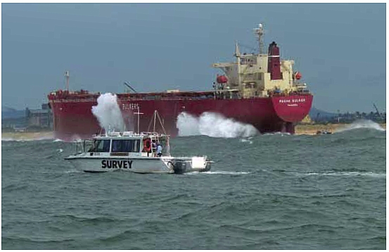
The Pasha Bulker (a coal carrier) ran aground off Newcastle in 2007 during a
significant storm event and surveyors from the Newcastle Port Corporation were
actively involved in trying to refloat her. A hydrographic survey was conducted
through the surf zone which contributed to the salvage efforts for refloating
the ship. © Courtesy of Newcastle Port Corporation, Newcastle, New South Wales,
Australia.
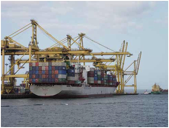
At 22,000 gross tonnes, vessels like the ANL Container Line Escort (a container
ship) draw well over 10 metres of water when fully loaded. Accommodating these
vessels presents a constant challenge for ports to maintain and publish up to
date depth information.
©
Courtesy of Sydney Ports Corporation, Sydney, New South Wales, Australia
Copyright © International Federation of Surveyors, November
2010
All rights reserved
International Federation of Surveyors (FIG)
Kalvebod Brygge 31–33
DK-1780 Copenhagen V
DENMARK
Tel. + 45 38 86 10 81
Fax + 45 38 86 02 52
E-mail: FIG@FIG.net
www.fig.net
Published in English
Copenhagen, Denmark
ISBN 978-87-90907-91-4
Published by
International Federation of Surveyors (FIG)
Front cover: left and right: © Courtesy of Sydney Ports Corporation, Sydney, New
South
Wales, Australia; centre: Courtesy of Newcastle Port Corporation, Newcastle, New
South
Wales, Australia
Back cover: © Courtesy of Sydney Ports Corporation, Sydney, New South Wales,
Australia
Design: International Federation of Surveyors, FIG
Printer: Oriveden Kirjapaino, Finland
|